C45-SATA
4HP Mezzanine I/O & Storage Module• Carrier Module for 1.8-Inch Micro SATA Solid State Drive • Internal or Removable
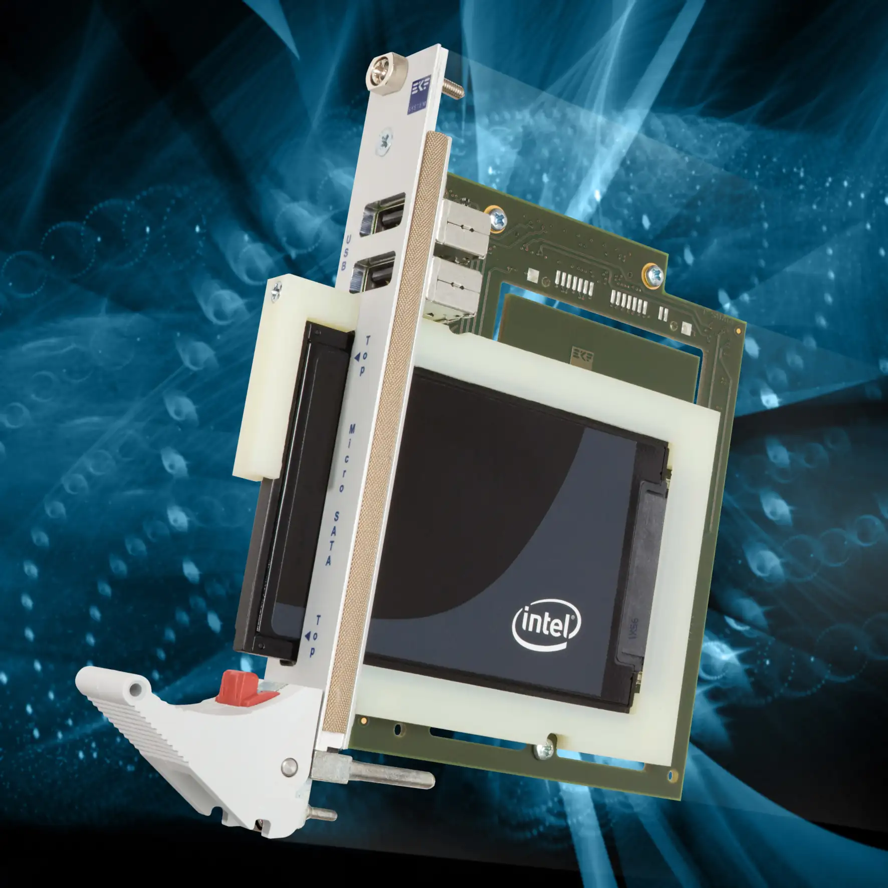
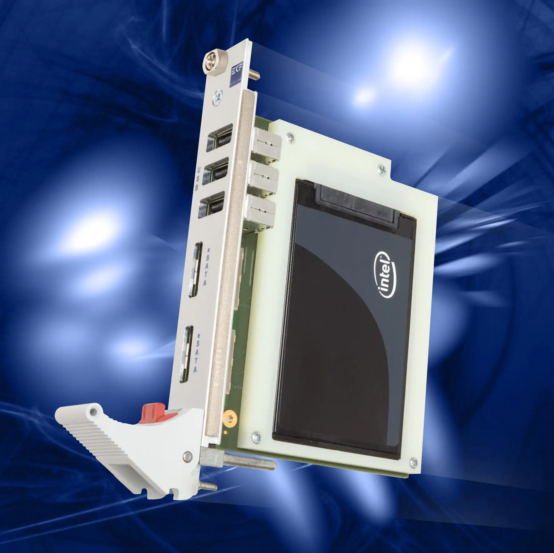
Available as a mezzanine add-on expansion board to the CCM-BOOGIE, PC1-GROOVE and successor CPU carrier cards, the main purpose of the C45-SATA is to provide SATA and USB connectors for front panel I/O. In addition, the C45-SATA can accommodate a 1.8-inch SATA SSD (Solid State Drive). Since only a few active components are required on the C45-SATA PCB, it is a reasonable low cost system expansion module.
Two eSATA connectors are available via the C45-SATA front panel, for attachment of external drives. The SATA channels may be either operated in a low level RAID (0/1) mode, or as universal non-RAID SATA ports, driven by the CPU carrier board SATA controller. In addition, three USB 2.0 receptacles are situated in the front panel. All connectors are individually protected from an overcurrent situation by electronic switches. The C45-SATA accommodates an 1.8-inch SATA drive, attached to the Micro SATA docking header. A solid state drive (SSD aka Flash Drive) according to SFF-8144 (54mm x 78.5mm x 5mm) is recommended for fast and rugged operation. As an alternate, a modified C45-SATA version is available which allows to remove/insert the solid state drive through the front panel.
The C45-SATA mounts on top of the CPU carrier board, with a 4HP pitch off-stand, resulting in a 8HP front panel for the entire dual-board assembly. For low cost applications, the C45-SATA can be populated with either the internal Micro SATA connector only (pure storage module function), or the front panel connectors only (pure I/O expansion module).
Downloads & Ressources
Documents
General Information
Drivers
Suitable Carrier Cards
Specifications
- Proprietary size mezzanine module 97mm x 100mm
- 4HP (20.32mm) mounting offset with respect to the CPU carrier board
- Typically delivered as a ready to use assembly unit (including the CCM-BOOGIE or successor CPU card)
- Mounting position right (on top of CPU board)
- 8HP front panel width (with front I/O connectors)
Simplified Block Diagram

